Wednesday, August 08, 2012

Smart 8051 Board


In this Board, Microcontroller interfaced with MT8870 DTMF IC, decoder ic, L293D, ULN2803, & segment, LED, LCD, and many more.

In this board every interfacing is done through male buck strip via jumper wires of 8 pins.....

so it is a complete board which provides u each and every interfacings which u need,...

like if u like this board......

Its cost is just INR 895

Tuesday, June 05, 2012

AVR Programmer

this is the circuit diagram or PCB Latyout of AVR Programmer uses DB9 Connector
i am going to upload 1 more image later which is used to show Component places....


Friday, May 25, 2012

Program for LED Blinking in Fashion

#include<8051.h>
#include<stdio.h>
void delay (int time)
{
unsigned int i,j;
for (i=0;i<=time*10;i++)
{
for (j=0;j<=time*10;j++)
{
}}}
void main()
{
P1=0xff;
while(1)
{
P1=0x00;
delay(10);
P1_0=1;
delay(10);
P1_1=1;
delay(10);
P1_2=1;
delay(10);
P1_3=1;
delay(10);
P1_4=1;
delay(10);
P1_5=1;
delay(10);
P1_6=1;
delay(10);
P1_7=1;
delay(10);


P1=0x00;
delay(10);
P1_7=1;
delay(10);
P1_6=1;
delay(10);
P1_5=1;
delay(10);
P1_4=1;
delay(10);
P1_3=1;
delay(10);
P1_2=1;
delay(10);
P1_1=1;
delay(10);
P1_0=1;
delay(10);


P1=0x00;
delay(10);
P1=0x81;
delay(10);
P1=0xc3;
delay(10);
P1=0xe7;
delay(10);
P1=0xff;
delay(10);


P1=0x00;
delay(10);
P1=0x18;
delay(10);
P1=0x3c;
delay(10);
P1=0x7e;
delay(10);
P1=0xff;
delay(10);


P1=0x00;
delay(15);
P1_0=1;
delay(15);
P1_1=1;
delay(15);
P1_2=1;
delay(15);
P1_3=1;
delay(15);
P1_4=1;
delay(15);
P1_5=1;
delay(15);
P1_6=1;
delay(15);
P1_7=1;
delay(15);


P1=0x00;
delay(15);
P1_7=1;
delay(15);
P1_6=1;
delay(15);
P1_5=1;
delay(15);
P1_4=1;
delay(15);
P1_3=1;
delay(15);
P1_2=1;
delay(15);
P1_1=1;
delay(15);
P1_0=1;
delay(15);


P1=0x00;
delay(15);
P1=0x81;
delay(15);
P1=0xc3;
delay(15);
P1=0xe7;
delay(15);
P1=0xff;
delay(15);


P1=0x00;
delay(15);
P1=0x18;
delay(15);
P1=0x3c;
delay(15);
P1=0x7e;
delay(15);
P1=0xff;
delay(15);


P1=0x00;
delay(15);
P1=0x80;
delay(15);
P1=0x40;
delay(15);
P1=0x20;
delay(15);
P1=0x10;
delay(15);
P1=0x08;
delay(15);
P1=0x04;
delay(15);
P1=0x02;
delay(15);
P1=0x01;
delay(15);


P1=0x00;
delay(15);
P1=0x01;
delay(15);
P1=0x02;
delay(15);
P1=0x04;
delay(15);
P1=0x08;
delay(15);
p1=0x10;
delay(15);
P1=0x20;
delay(15);
P1=0x40;
delay(15);
P1=0x80;
delay(15);


P1=0x00;
delay(15);
P1=0x81;
delay(15);
P1=0x42;
delay(15);
P1=0x24;
delay(15);
P1=0x18;
delay(15);


P1=0x00;
delay(15);
P1=0x18;
delay(15);
P1=0x24;
delay(15);
P1=0x42;
delay(15);
P1=0x81;
delay(15);
}
}

Program for LCD interface with 8051

#include<REGX51.H>
#include<stdio.h>
sfr ldata=0x90;
sbit rs=P2^0;
sbit rw=P2^1;
sbit en=P2^2;
void delay(int a);
void lcdcmd(unsigned char value);
void lcddata(unsigned char value);

void lcdcmd(unsigned char value)
{
ldata=value;
rs=0;
rw=0;
en=1;
delay(2);
en=0;
return;
}

void lcddata(unsigned char value)
{
ldata=value;
rs=1;
rw=0;
en=1;
delay(2);
en=0;
return;
}

void delay(int a)
{
unsigned int i,j;
for(i=0;i<=100;i++)
{
for(j=0;j<=10*a;j++)
{
}}}

void main()
{
P1=0x00;
lcdcmd(0x38);
delay(2);
lcdcmd(0x0E);
delay(2);
lcdcmd(0x01);
delay(2);
lcdcmd(0x06);
delay(2);

while(1)
{
lcdcmd(0x82);
delay(10);
lcddata(‘T’);
delay(10);
lcddata(‘E’);
delay(10);
lcddata(‘C’);
delay(10);
lcddata(‘H’);
delay(10);
lcddata(‘F’);
delay(10);
lcddata(‘O’);
delay(10);
lcddata(‘R’);
delay(10);
lcddata(‘M’);
delay(10);
lcddata(‘E’);
delay(10);
lcddata(‘R’);
delay(10);
lcddata(‘S’);
delay(10);
lcdcmd(0xC2);
delay(10);
lcddata(‘T’);
delay(10);
lcddata(‘E’);
delay(10);
lcddata(‘C’);
delay(10);
lcddata(‘H’);
delay(10);
lcddata(‘N’);
delay(10);
lcddata(‘O’);
delay(10);
lcddata(‘L’);
delay(10);
lcddata(‘O’);
delay(10);
lcddata(‘G’);
delay(10);
lcddata(‘I’);
delay(10);
lcddata(‘E’);
delay(10);
lcddata(‘S’);
delay(10);
}}

Program for Keypad interface with 8051 and Displayed on LCD

#include<8051.h>
#include
#define EN P1_7
#define RW P1_6
#define RS P1_5
#define DL P3
#define c0 P2_0
#define c1 P2_1
#define c2 P2_2
#define c3 P2_3
#define r1 P2_4
#define r2 P2_5
#define r3 P2_6
#define r4 P2_7

void delay(int time);
void lcd_init();
void cmd(char cmdbyte);
void dataa(char ch);
void clear();
void mov_cur(char pos);
void writeat(char ch,char pos);
void enterword();

void delay(int time)
{
int i,j;
for(i=0;i
{
for(j=0;j
{
}
}
}

void cmd(char cmdbyte)
{
EN=1;
RW=0;
RS=0;
DL=cmdbyte;
EN=0;
delay(10);
}

void dataa(char ch)
{
EN=1;
RW=0;
RS=1;
DL=ch;
EN=0;
delay(10);
}

void lcd_init()
{
cmd(0x38);
cmd(0x05);
cmd(0x0F);
cmd(0x06);
}

void clear()
{
cmd(0x01);
}

void mov_cur(char pos)
{
cmd(pos);
}

void keypad()
{
if ((r1==0) && (r2==1) && (r3==1) && (r4==1))
{
if ((c0==0) && (c1==1) && (c2==1) && (c3==1))
{
dataa('a');
}
if ((c0==1) && (c1==0) && (c2==1) && (c3==1))
{
dataa('b');
}
if ((c0==1) && (c1==1) && (c2==0) && (c3==1))
{
dataa('c');
}
if ((c0==1) && (c1==1) && (c2==1) && (c3==0))
{
dataa('d');
}
}
if ((r1==1) && (r2==0) && (r3==1) && (r4==1))
{
if ((c0==0) && (c1==1) && (c2==1) && (c3==1))
{
dataa('e');
}
if ((c0==1) && (c1==0) && (c2==1) && (c3==1))
{
dataa('f');
}
if ((c0==1) && (c1==1) && (c2==0) && (c3==1))
{
dataa('g');
}
if ((c0==1) && (c1==1) && (c2==1) && (c3==0))
{
dataa('h');
}
}
if ((r1==1) && (r2==1) && (r3==0) && (r4==1))
{
if ((c0==0) && (c1==1) && (c2==1) && (c3==1))
{
dataa('i');
}
if ((c0==1) && (c1==0) && (c2==1) && (c3==1))
{
dataa('j');
}
if ((c0==1) && (c1==1) && (c2==0) && (c3==1))
{
dataa('k');
}
if ((c0==1) && (c1==1) && (c2==1) && (c3==0))
{
dataa('l');
}
}
if ((r1==1) && (r2==1) && (r3==1) && (r4==0))
{
if ((c0==0) && (c1==1) && (c2==1) && (c3==1))
{
dataa('m');
}
if ((c0==1) && (c1==0) && (c2==1) && (c3==1))
{
dataa('n');
}
if ((c0==1) && (c1==1) && (c2==0) && (c3==1))
{
dataa('o');
}
if ((c0==1) && (c1==1) && (c2==1) && (c3==0))
{
dataa('p');
}
}
}

void main()
{
P1=0xFF;
P2=0xFF;
P3=0xFF;
lcd_init();
clear();
RW=0;
keypad();
delay(10);
}

Program for ADC interface with 8051

#include<8051.h>
#include
void delay (int time)
{
unsigned int i,j;
for (i=0;i<=time*10;i++)
{
for (j=0;j<=time*10;j++)
{
}
}
}
void adc( )
{
if ((P1_7==0 && P1_6==0 && P1_5==0 && P1_4==0 && P1_3==0 && P1_2==0 && P1_1==0 && P1_0==0))
{
P0=0xc0;
}
if ((P1_7==0 && P1_6==0 && P1_5==0 && P1_4==0 && P1_3==0 && P1_2==0 && P1_1==0 && P1_0==1))
{
P0=0xf9;
}
if ((P1_7==0 && P1_6==0 && P1_5==0 && P1_4==0 && P1_3==0 && P1_2==0 && P1_1==1 && P1_0==0))
{
P0=0xa4;
}
if ((P1_7==0 && P1_6==0 && P1_5==0 && P1_4==0 && P1_3==0 && P1_2==0 && P1_1==1 && P1_0==1))
{
P0=0xb0;
}
if ((P1_7==0 && P1_6==0 && P1_5==0 && P1_4==0 && P1_3==0 && P1_2==1 && P1_1==0 && P1_0==0))
{
P0=0x99;
}
if ((P1_7==0 && P1_6==0 && P1_5==0 && P1_4==0 && P1_3==0 && P1_2==1 && P1_1==0 && P1_0==1))
{
P0=0x92;
}
if ((P1_7==0 && P1_6==0 && P1_5==0 && P1_4==0 && P1_3==0 && P1_2==1 && P1_1==1 && P1_0==0))
{
P0=0x82;
}
if ((P1_7==0 && P1_6==0 && P1_5==0 && P1_4==0 && P1_3==0 && P1_2==1 && P1_1==1 && P1_0==1))
{
P0=0xf8;
}
if ((P1_7==0 && P1_6==0 && P1_5==0 && P1_4==0 && P1_3==1 && P1_2==0 && P1_1==0 && P1_0==0))
{
P0=0x80;
}
if ((P1_7==0 && P1_6==0 && P1_5==0 && P1_4==0 && P1_3==1 && P1_2==0 && P1_1==0 && P1_0==1))
{
P0=0x90;
}
}
void main( )
{
P0=0xff;
P1=0xff;
delay(10);
while(1)
{
adc( );
delay(10);
}
}

Audio and Video Capturing Robot using RF Communication


In our project keypad is interfaced with RF Transmitter through RF Encoder, so if we press any of the key from forward, backward, right and left, then after pressing any it will generate a signal Which is of 4 bit corresponding to four keys, because firstly we are providing high logic which means 1 and in electronics it means we are providing 5 volt supply to each of the keys, and another pin of keypad is connected is connected to ground so by pressing any key we provide logic 0 means ground. Thus one bit of data has been changed and remaining 3 data remains unchanged, means if we press forward key then we are sending signal 0111 which is of four bit. Now this 4 bit data is converted to 1 bit by RF Encoder (HT12E) which is then transmitted to receiving end via RF Transmitter. Then particular 1 bit data is received at receiving end through RF Receiver, which is then provided to RF Decoder whose work is to decode the data which is being transmitted from transmitter end or through the keypad. Thus 1 bit data is received which is then converted to 4 bit Through RF decoder (HT12D) which is then given to Microcontroller where we programmed our microcontroller, here the 2 motors which are interfaced with microcontroller are moving in either direction through H-Bridge (L293D) which is known as motor driver because this IC is Used to drive 2 dc motors, and another function of this motor driver is to protect our microcontroller from back EMF generated through DC Motor because in this IC Buffer is used which works as feedback diode. Now the motor runs in forward, backward, right and left direction through motors, so by pressing any key the Robot moved in that particular direction. Now for extra features we installed or placed wireless camera over the robot, so the camera captures any audio and video is directly transferred to Television through Camera receiver and TV Tuner. Thus we can easily capture anything through our Project without going anywhere. This wireless robot with camera is very much effective in Warfield zone as we can capture audio and video as well as in night also by attaching Night Vision Camera. There are several Applications of this Robot.

PCB of Basic AVR ckt: -


Schematic Diagram of Basic AVR: -

Schematic Diagram of RF Transmitter: -

PCB Layout of RF Transmitter: -

Schematic Diagram of RF Receiver: -

PCB Layout RF Receiver: -


Program with PPT of this Project can be downloaded through below given link


To download Project report click the link given below


To download the video related to project click the link given below


Sunday, April 01, 2012

Interfacing Temperature Sensor – LM35 with AVR Microcontroller

By interfacing different types of sensors with our MCU we can sense the environment and take decisions, in this way we can create "smart" applications. There are wide variety of sensors available. In this tutorial we will learn about a popular sensor LM35 which is precision centigrade temperature sensor. It can be used to measure temperature with accuracy of 0.5 degree centigrade. We can interface it easily with AVR MCUs and can create thermometers, temperature controller, fire alarms etc.

LM35

LM35 by National Semiconductor is a popular and low cost temperature sensor. It is also easily available. It has three pins as follows.
The Vcc can be from 4V to 20V as specified by the datasheet. To use the sensor simply connect the Vcc to 5V ,GND to Gnd and the Out to one of the ADC (analog to digital converter channel). The output linearly varies with temperature. The output is
10MilliVolts per degree centigrade.
So if the output is 310 mV then temperature is 31 degree C. To make this project you should be familiar with the ADC of AVRs and also using seven segment displays. Please refer to following articles.
  • Using the ADC of AVRs.
  • Using Seven Segment Display.
  • Using Seven Segment Display in Multiplexed Mode.
The resolution of AVRs ADC is 10bit and for reference voltage we are using 5V so the resolution in terms of voltage is
5/1024 = 5mV approx
So if ADCs result corresponds to 5mV i.e. if ADC reading is 10 it means
10 x 5mV = 50mV
You can get read the value of any ADC channel using the function
ReadADC(ch);
Where ch is channel number (0-5) in case of ATmega8. If you have connected the LM35's out put to ADC channel 0 then call
adc_value = ReadADC(0)
this will store the current ADC reading in variable adc_value. The data type of adc_value should be int as ADC value can range from 0-1023.
As we saw ADC results are in factor of 5mV and for 1 degree C the output of LM35 is 10mV, So 2 units of ADC = 1 degree.
So to get the temperature we divide the adc_value by to
temperature = adc_value/2;
Finally you can display this value in either the 7 segment displays by using the Print() function we developed in last tutorial or you can display it in LCD Module. To know how to display integer in 7 segment displays and LCD Modules see the articles.
  • Multiplexed Seven Segment Display.
  • Using LCD Modules with AVRs.
In this tutorial I have used three 7 segment displays to show the temperature. I have used the xBoard MINI - ATmega8 board to make the project. The complete program is given below.

Program (AVR GCC)


#include
#include
#include
#define SEVEN_SEGMENT_PORT PORTD
#define SEVEN_SEGMENT_DDR DDRD
uint8_t digits[3]; //Holds the digits for 3 displays
void SevenSegment(uint8_t n,uint8_t dp)
{
/*
This function writes a digits given by n to the display
the decimal point is displayed if dp=1
Note:
n must be less than 9
*/
if(n<10)
{
switch (n)
{
case 0:
SEVEN_SEGMENT_PORT=0b00000011;
break;
case 1:
SEVEN_SEGMENT_PORT=0b10011111;
break;
case 2:
SEVEN_SEGMENT_PORT=0b00100101;
break;
case 3:
SEVEN_SEGMENT_PORT=0b00001101;
break;
case 4:
SEVEN_SEGMENT_PORT=0b10011001;
break;
case 5:
SEVEN_SEGMENT_PORT=0b01001001;
break;
case 6:
SEVEN_SEGMENT_PORT=0b01000001;
break;
case 7:
SEVEN_SEGMENT_PORT=0b00011111;
break;
case 8:
SEVEN_SEGMENT_PORT=0b00000001;
break;
case 9:
SEVEN_SEGMENT_PORT=0b00001001;
break;
}
if(dp)
{
//if decimal point should be displayed
//make 0th bit Low
SEVEN_SEGMENT_PORT&=0b11111110;
}
}
else
{
//This symbol on display tells that n was greater than 9
//so display can't handle it
SEVEN_SEGMENT_PORT=0b11111101;
}
}
void Wait()
{
uint8_t i;
for(i=0;i<10;i++)
{
_delay_loop_2(0);
}
}
void Print(uint16_t num)
{
uint8_t i=0;
uint8_t j;
if(num>999) return;
while(num)
{
digits[i]=num%10;
i++;
num=num/10;
}
for(j=i;j<3;j++) digits[j]=0;
}
void InitADC()
{
ADMUX=(1<
ADCSRA=(1<
}
uint16_t ReadADC(uint8_t ch)
{
//Select ADC Channel ch must be 0-7
ch=ch&0b00000111;
ADMUX|=ch;
//Start Single conversion
ADCSRA|=(1<
//Wait for conversion to complete
while(!(ADCSRA & (1<
//Clear ADIF by writing one to it
ADCSRA|=(1<
return(ADC);
}
void main()
{
uint16_t adc_value;
uint8_t t;
// Prescaler = FCPU/1024
TCCR0|=(1<
//Enable Overflow Interrupt Enable
TIMSK|=(1<
//Initialize Counter
TCNT0=0;
//Port C[2,1,0] as out put
DDRB|=0b00000111;
PORTB=0b00000110;
//Port D
SEVEN_SEGMENT_DDR=0XFF;
//Turn off all segments
SEVEN_SEGMENT_PORT=0XFF;
//Enable Global Interrupts
sei();
//Enable ADC
InitADC();
//Infinite loop
while(1)
{
//Read ADC
adc_value=ReadADC(0);
//Convert to degree Centrigrade
t=adc_value/2;
//Print to display
Print(t);
//Wait some time
Wait();
}
}
ISR(TIMER0_OVF_vect)
{
static uint8_t i=0;
if(i==2)
{
i=0;
}
else
{
i++;
}
PORTB=~(1<
SevenSegment(digits[i],0);
}

Sunday, March 25, 2012

How to interface keypad with AVR microcontroller (ATmega16)


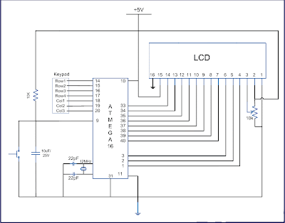
Keypad is most widely used input device to provide input from the outside world to the microcontroller. The keypad makes an application more users interactive. The concept of interfacing a keypad with the ATmega16 is similar to interfacing it with any other microcontroller. The article of Interfacing keypad with 8051 can be referred for detailed description of the methodology used here. This article explains the interfacing of a 4x3 keypad with AVR Microcontroller (ATmega16) and displaying the output on a LCD.
The algorithm and detailed explanation for keypad interfacing is given in above mentioned article. The brief steps to interface the keypad with AVR are written below:
1. Configure the row pins or column pins.
2. Make all output pins to low and input pins to high.
3. Keep monitoring the port value, where the key pad is connected.


Program related to this Project: -

// Program to get input from keypad and display it on LCD.
#include
#include
#define pad PORTD
#define r1 PD0
#define r2 PD1
#define r3 PD2
#define r4 PD3
#define c1 PD4
#define c2 PD5
#define c3 PD6
void check1(void);
void check2(void);
void check3(void);
void check4(void);
#define LCD_DATA PORTA //LCD data port
#define ctrl PORTB
#define en PB2 //enable signal
#define rw PB1 //read/write signal
#define rs PB0 //resister select signal
void LCD_cmd(unsigned char cmd);
void init_LCD(void);
void LCD_write(unsigned char data);
unsigned int press;
int main()
{
unsigned char value;
DDRA=0xff; //LCD_DATA port as output port
DDRB=0x07; //signal as out put
DDRD=0x0F;
pad=0xf0;
init_LCD(); //initialization of LCD
LCD_write_string("press a key");
LCD_cmd(0xc0);
while(1)
{
PORTD=0xF0; //set all the input to one
value=PIND; //get the PORTD value in variable “value”
if(value!=0xf0) //if any key is pressed value changed
{
check1();
check2();
check3();
check4();
}
}
return 0;
}
void check1(void)
{
//DDRD = 0xf0;
pad =0b11111110;
//pad &= (0<
_delay_us(10);
if(bit_is_clear(PIND,c1))
LCD_write('1');
else if(bit_is_clear(PIND,c2))
LCD_write('2');
else if(bit_is_clear(PIND,c3))
LCD_write('3');
}
void check2(void)
{
pad=0b11111101;
/pad &= (0<
_delay_us(10);
if(bit_is_clear(PIND,c1))
LCD_write('4');
else if(bit_is_clear(PIND,c2))
LCD_write('5');
else if(bit_is_clear(PIND,c3))
LCD_write('6');
}
void check3(void)
{
pad=0b11111011;
//pad &= (0<
_delay_us(10);
if(bit_is_clear(PIND,c1))
LCD_write('7');
else if(bit_is_clear(PIND,c2))
LCD_write('8');
else if(bit_is_clear(PIND,c3))
LCD_write('9');
}
void check4(void)
{
pad =0b11110111;
//pad &= (0<
_delay_us(10);
if(bit_is_clear(PIND,c1))
LCD_write('#');
else if(bit_is_clear(PIND,c2))
LCD_write('0');
else if(bit_is_clear(PIND,c3))
LCD_write('*');
}
void init_LCD(void)
{
LCD_cmd(0x38); //initializtion of 16X2 LCD in 8bit mode
_delay_ms(1);
LCD_cmd(0x01); //clear LCD
_delay_ms(1);
LCD_cmd(0x0E); //cursor ON
_delay_ms(1);
LCD_cmd(0x80); // ---8 go to first line and --0 is for 0th position
_delay_ms(1);
return;
}
void LCD_cmd(unsigned char cmd)
{
LCD_DATA=cmd;
ctrl =(0< // making RS and RW as LOW and EN as HIGH
_delay_ms(1);
ctrl =(0< // making RS, RW , LOW and EN as LOW
_delay_ms(50);
return;
}
void LCD_write(unsigned char data)
{
LCD_DATA= data;
ctrl = (1< // making RW as LOW and RS, EN as HIGH
_delay_ms(1);
ctrl = (1< // making EN and RW as LOW and RS HIGH
_delay_ms(50); // give a 10 milli second delay to get thigs executed
return ;
}
void LCD_write_string(unsigned char *str) //take address vaue of the string in pionter *str
{
int i=0;
while(str[i]!='\0') // loop will go on till the NULL charaters is soon in string
{
LCD_write(str[i]); // sending data on CD byte by byte
i++;
}
return;
}
while(1)
{
PORTD=0xF0; //set all the input to one
value=PIND; //get the PORTD value in variable “value”
if(value!=0xf0) //if any key is pressed value changed
{
check1();
check2();
check3();
check4();
}
}
4. If there is any change in port value, make one of the output pin of port to zero and rest all high.
void check1(void)
{
//DDRD = 0xf0;
pad =0b11111110;
//pad &= (0<
_delay_us(10);
if(bit_is_clear(PIND,c1))
LCD_write('1');
else if(bit_is_clear(PIND,c2))
LCD_write('2');
else if(bit_is_clear(PIND,c3))
LCD_write('3');
}
5. If any of input pin found zero, write the particular pin data to LCD, else continue with the step (4).